I²C + AI = crazy fast simple hardware prototyping
Historically, two things have made prototyping even simple hardware annoying for me:
- Getting the wiring right, especially with the variance in how different peripherals connect
- Writing the code to read from/write to the peripherals, often requiring wading through poorly-translated spec sheets
But recently, I’ve done a couple hack projects that have taken no time at all, thanks to peripherals with I²C/Qwiic/Stemma connectors solving bullet number 1, and AI coding assistance solving bullet number 2.
This post will walk through a step-by-step tutorial of a recent toy hardware project that took just 30 minutes to get operational after opening up the sensors I ordered.

30 minute project: Office Environmental Monitor
The goal: make an environmental sensor for my office that monitorsTracking “true” VOC levels is hard with commodity hardware, and subject to a bunch of tricky nuances. Here’s a thread on the AirGradient forums if you want to learn more. The AirGradient uses the Sensirion SGP41, and I went with the SGP30. The SGP41 outputs an arguably-more-informative VOC index measurement to show changes in concentration, whereas the SGP30 outputs a proper TVOC measurement in ppb, but there are issues with it (hence the change to an index approach in the SGP4x next-generation sensor).:
- the current light spectrum (including UV and IR) and brightness (see All light is not created equal for why this matters)
- particulate matter of various sizes in the air
- CO2 and VOC levels
- plus temperature, humidity, and anything else I could easily pick up
Basically: how healthy is my office right now? People are increasingly carrying CO2 monitors, but I think we can do even better.
Here’s a preview of the final product booting up and running (sped up):
I went shopping on Adafruit and gotThis gets way cheaper if you’re okay without a “true” CO2 measurement (the most expensive component, ~35% of the total sensor costs). The SGP30, which we want anyway for VOCs, outputs estimated CO2 based on H2 concentrations. The SCD-41 is a true photoacoustic CO2 sensor, which is a more expensive component.:
Across these, I’d be able to read:
- light quality
- 8-band (violet, indigo, blue, cyan, green, yellow, orange, red) light spectrum distribution
- UV and NIR indices
- illuminance
- air quality
- 6 sizes of (0.3, 0.5, 1.0, 2.5, 5, and 10 micron) particulate matter
- true CO2
- TVOCs
- temperature
- humidity
- (and a few more characteristics too!)
At the time I didn’t realize Adafruit made an I²C interface version of the PMS5003 air quality sensor, so I might have swapped for that in place of the sensor with breadboard adapter kit With that said, I would have some concerns about the current draw of the PMS5003 and it screwing up the I²C chain, so maybe the standalone breadboard adapter is better anyway. Don’t tell me I didn’t warn you!.
You’ll also need a few other things I had laying around, including a CircuitPython-compatible development board (I used the Itsy Bitsy M4 Express), a breadboard, some jumper wires, and an I2C-male-to-4-header-pin cable. I think these would cover you:
| Component | Cost |
|---|---|
| CircuitPython Starter Kit with Adafruit Itsy Bitsy M4 | $24.95 |
| JST PH 2mm 4-Pin to Male Header Cable | $1.50 |
| Subtotal | $26.45 |
| Total with above | $165.50 |
Once you get all this stuff and unpack it, we can get to work. Start your timers!
Step 1: Wire everything up (7 minutes)
I²C is a protocol invented by Philips Semiconductors back in 1982, but now in use by companies like Sparkfun and Adafruit to make dead-simple peripheral connections. Adafruit calls their version of it “Qwiic” and Sparkfun calls theirs “Stemma.” For our simple purposes, they’re all basically equivalent.
One of the awesome things about I²C (and the reason it solves my original problem #1) is that you can wire up all the peripherals in series, one after another. And as long as they have different I²C addresses, it just works. The data flows through the whole chain of sensors and ends up where it needs to be.
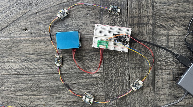
So the wiring for this project is incredibly simple, despite the number of sensors:
- connect the five I²C sensors (SCD41, SGP30, AS7341, TSL2591, LTR390) to each other in a chain with the I²C cables, in any order
- connect the first one with your I²C-to-male-header cable
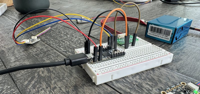
- put the dev board on your breadboard and connect the male headers from the previous cable as follows:
- black into the ground row
- red into 3.3V
- yellow into SCL
- blue into SDA
- plug the PMS5003 adapter cable into the PMS5003 sensor, and then stick the breadboard adapter into the breadboard
- take three male-to-male jumper cables and put them:
- PMS5003 adapter VCC to dev board VHI (or USB, if your board doesn’t have a VHI)
- adapter GND to board G
- adapter TXD to board RX
- plug a micro usb cable into your dev board and prepare to plug the other end into your computer
Here’s a snapshot. No, it ain’t pretty — it’s a 30 minute project!

Step 2: Install CircuitPython & libraries (5 minutes)
Next up, plug the dev board’s USB cable into your computer. It should show up as an external drive.
Find your board on the CircuitPython website and download the appropriate .UF2 file. This will allow your board to run CircuitPython code, which is a version of Python specifically made for (… can you guess?) programming electronics / microcontrollers.
Also download the Adafruit “bundle” of CircuitPython libraries. This has everything you’ll need to connect to your sensors.
Now press the reset button twice on your board to get it into bootloader mode, and then copy the .UF2 file over to the drive. It will disappear for a minute, and when it comes back, the drive should be named CIRCUITPYTHON.
Go into it and make a lib folder. Then go into your Adafruit bundle and select the following items:
- adafruit_as7341.mpy
- adafruit_bus_device/
- adafruit_ltr390.mpy
- adafruit_pm25/
- adafruit_register/
- adafruit_scd4x.mpy
- adafruit_sgp30.mpy
- adafruit_tsl2591.mpy
And copy them all over into the lib folder on your CIRCUITPYTHON drive.
Now we have CircuitPython installed and all the libraries we need to interface with our sensors!
Step 3: Code it up (7 minutes)
Plugging six different sensors into a board, each with a different library and way of reading data, used to be a nightmare. I’d be reading through library documentation to get the special incantation required to get each of them working.
But this is a place where AI really shines.
I made a new directory, copied the lib/ directory into it, opened up a new file named code.py in Cursor, went to the agent (Claude Sonnet 3.7), and said something like:
I want to read data off the following sensors: SCD41, SGP30, AS7341, TSL2591, LTR390 (all from Adafruit, connected with I2C) and a PMS5003 (connected over UART). My development board is an Itsy Bitsy M4 Express running CircuitPython.
The libraries (several with examples) are all in here: @lib/
Please import the libraries and make a simple script that connects to all these sensors and then reads all the available data off the sensors every 10 seconds, outputting it in print() statements
Include some simple status print() statements, like when the connections are happening and sampling is beginning.
I hit enter, waited three minutes for the agent to write it up, and there we were. Barely had to lift a finger.
Step 4: Run it (1 minute)
Then, go into your terminal and type (I’m on macOS) ls /dev/tty.* and you will see something that looks like /dev/tty.usbmodem211301
Copy that and run (replace path with what you copied) screen /dev/tty.usbmodem211301 115200
(115200 is the speed / baud rate of that board — yours may vary.)
Take the code.py file and drag it over to the CIRCUITPYTHON drive, replacing the current code.py file.
And… it should pretty magically start working, printing out the results of the sensor readings every 10 seconds.
Again, here’s that same screengrab of the output (after I prettied it up a bit):
At this point, you should have 10 minutes left in our 30 minute project. Or, maybe not — if you’re anything like me, you probably used up those 10 minutes sorting out something you messed up (like swapping TX / RX pins as I always do).
What next?
I find it pretty remarkable that in less than an hour, it’s possible to have a fully-functional multimodal environmental sensor up and running. Sure, it’s basic And: you should still read the docs, make sure you’re calibrating all the sensors correctly and giving them all the data they need (some are more accurate when you feed in e.g. humidity) and interpreting the data correctly., but… we’re talking about thirty minutes and $150 or less for way more data than you get from any commercial environment sensor I can find (are there any that give you light spectrum data?).
I’ve fumbled my way through a lot of hardware hack projects, getting stuck in the mud on weird nuances of reading data from sensors or connecting them. That — at least for me — is not the fun stuff. But I’m realizing that now, with modern connectors and AI, you can skip that and get to the fun.
What are the fun next steps? Things like:
- Improving the output visually (see my screen recording above)
- Doing more analysis on the output to make it informative, triggering alerts, etc.
- Adding a screen so the device can be standalone
- Designing and printing a case/stand so it’s not a tangled mess of wires and can be placed in a more accurate location (i.e. light sensors should be as close to my eye position/perspective as possible)
- Getting this off a breadboard and soldering it
- Connecting to internet or Bluetooth to pass data elsewhere
I’m planning on continuing to improve this device. I actually think it’s quite useful.
If you try building something similar, let me know!
Looking for more to read?
Want to hear about new essays? Subscribe to my roughly-monthly newsletter recapping my recent writing and things I'm enjoying:
And I'd love to hear from you directly: andy@andybromberg.com